Mesh Generation & Optimization
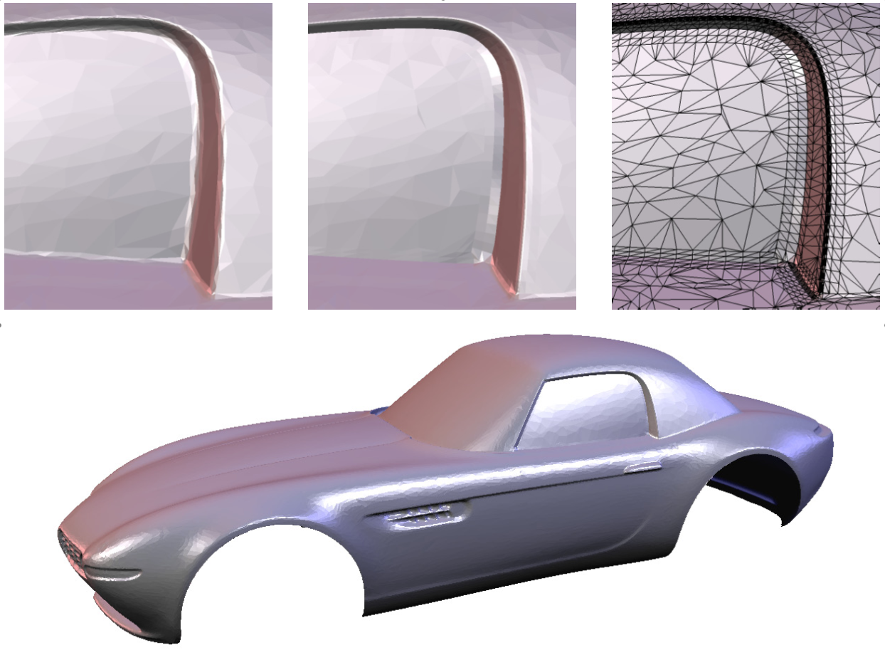
Engineering applications and numerical simulations require a faithful approximation of the involved geometric models. In the case of technical data sets, sharp or highly curved edges and corners, so-called geometric features, carry crucial shape information and therefore have to be represented accurately. In order to minimize geometric aliasing the mesh tessellation needs to be aligned to the feature lines, i.e., to the principal curvature directions of the underlying geometry. To this end, we extend the well known Marching Cubes algorithm in order to detect and reconstruct sharp edges or corners when extracting an isosurface from a volumetric data set {$ cite 2001-emc %}. Figures 1 compares the standard and the extended Marching Cubes for a milling simulation, implemented by constructive solid geometry (CSG). In (Botsch & Kobbelt, 2001) a resampling strategy for anisotropically curved feature and blend regions is derived, with the goal to minimize geometric aliasing artifacts (Figure 2).


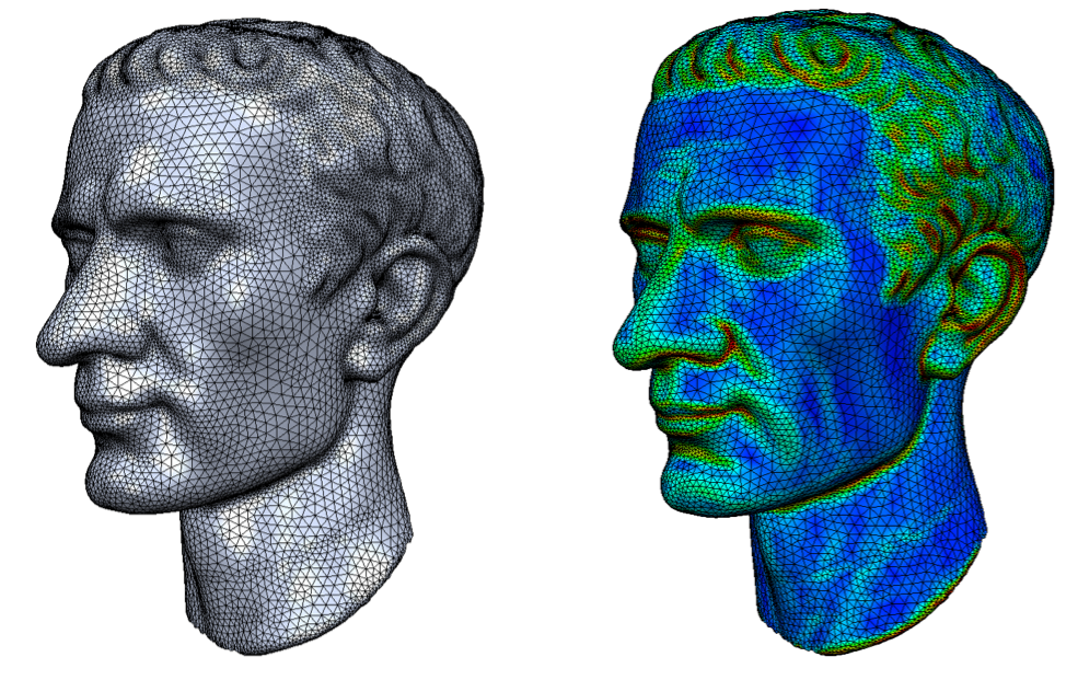
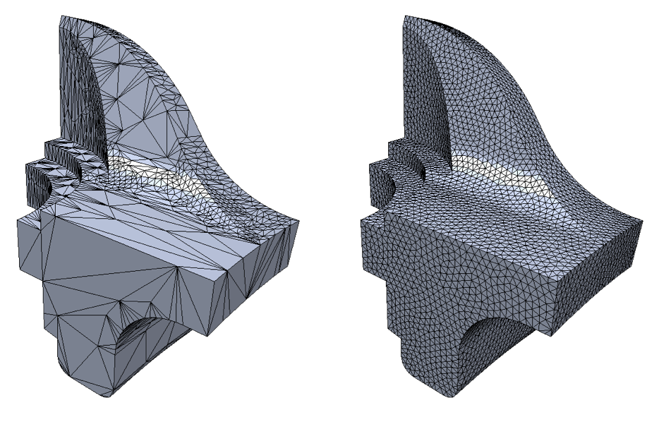
The robustness of numerical simulations strongly depends on the shape of triangles or tetrahedra in the surface or volume tessellation. While equilateral triangles allow for robust simulations, the extremely small and large angles in degenerate triangles prevent stable computations of areas or gradients. We can apply isotropic remeshing (Botsch & Kobbelt, 2004; Dunyach et al., 2013) for globally optimizing the tessellation using numerically robust equilateral triangles (Figures 3, 4). The latter method is fast enough for real-time remeshing in interactive modeling applications.


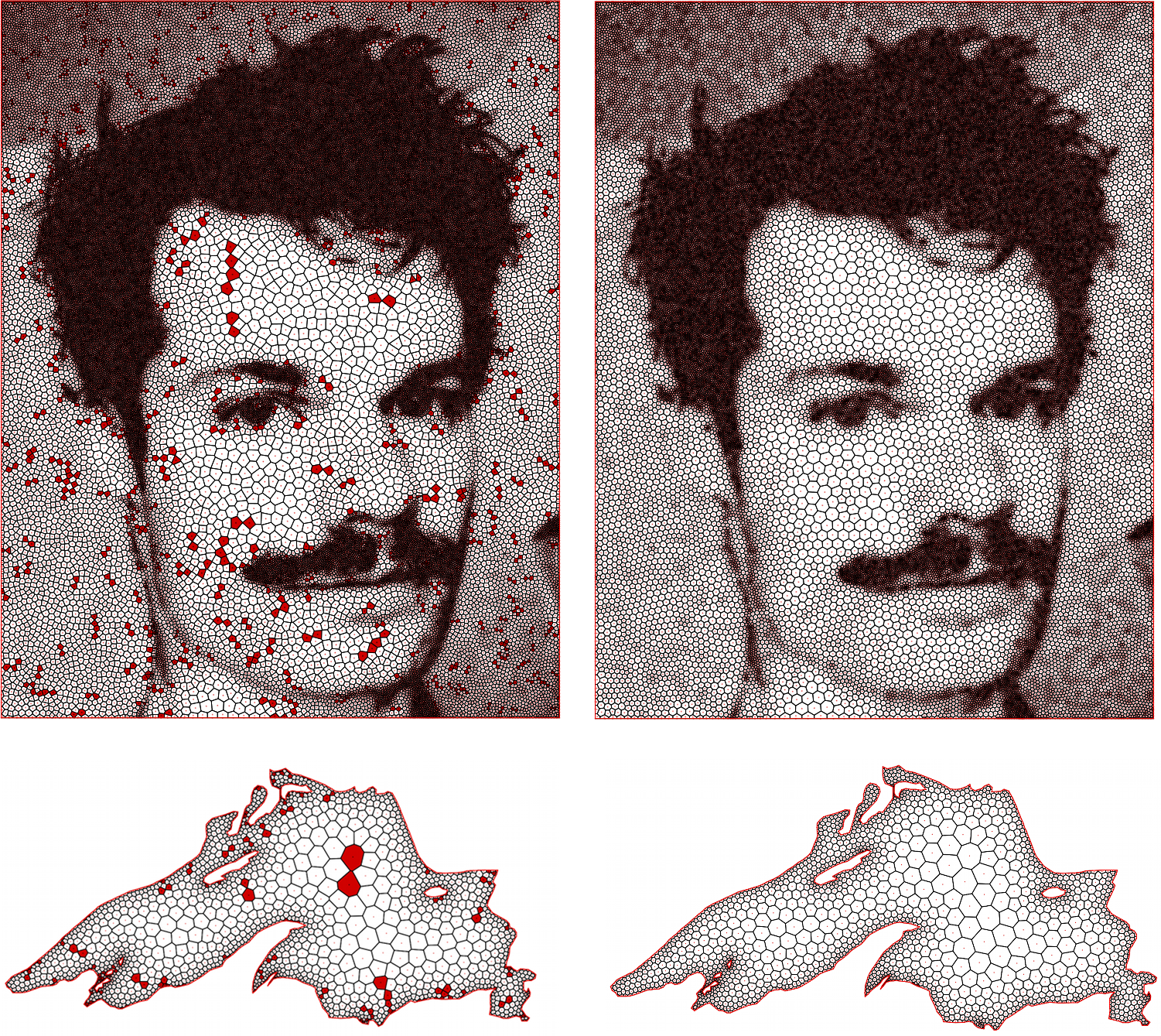
Classical simulation methods typically discretize the simulation domain into triangular or quadrilateral elements. In contrast, polygonal finite element methods allow for arbitrary polygonal elements. A widespread approach to mesh generation for polygonal finite elements are centroidal Voronoi tessellations (CVTs). While CVTs contain mostly well-shaped elements, they may also contain a number of ill-conditioned elements with short edges. These short edges are a major reason for numerical instabilities. In (Sieger et al., 2010) we present a method to effectively remove short edges from the Voronoi diagram by minimizing a carefully chosen energy functional (Figure 6).


