Physics-Based Simulation
Finite element methods are an important tool for simulating real-world behavior, for example in virtual reality applications such as surgery simulations, or in computer animation for feature films.
In computer graphics, surfaces or solid objects are typically represented by triangle meshes or tetrahedral meshes, respectively. While this allows for simple and efficient simulation codes, dynamically changing the simulation mesh, for instance due to cutting in medical applications or adaptive refinement in complex simulations, requires complex and error-prone remeshing. Our goal therefore is to generalize finite element methods to directly support arbitrary polyhedral elements, which effectively avoids the need for remeshing and thereby simplifies the simulation of fracture or cutting as well as adaptive refinement of the simulation mesh.
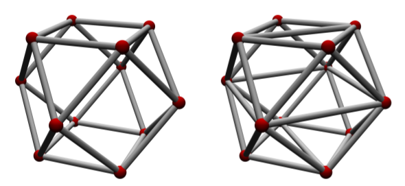
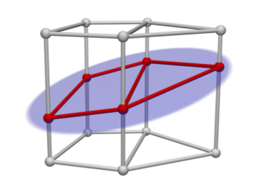
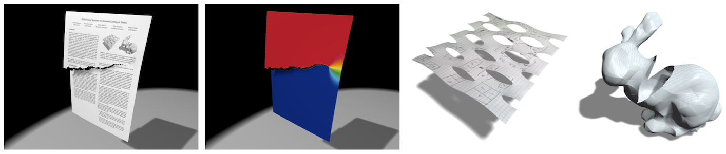
The main challenge is the construction of shape functions for general polyhedral elements that satisfy the requirements of a convergent FEM scheme. In (Wicke et al., 2007) we employ mean-value shape functions, which support convex polyhedral elements with triangulated faces (Figure 1, right). Using harmonic coordinates (Martin et al., 2008) even allows for non-convex polyhedra and only requires planar faces and linear edges, but not necessarily triangulated faces (Figure 1, left). Another approach is the discontinuous Galerkin method, which allows for discontinuous shape functions by weakly enforcing continuity between elements (Figure 2). This considerably increases the flexibility of the method, and in particular allows arbitrary polyhedra to be simulated (Kaufmann et al., 2009).
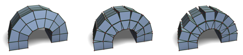
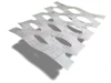
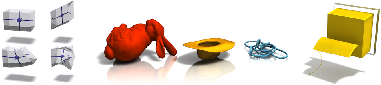
The support for arbitrary polyhedra in FEM schemes significantly simplifies cutting simulations, since the polyhedra resulting from splitting existing elements can directly be simulated without first having to be tessellated into tetrahedra (Figure 3). In comparison to a tetrahedral cutting simulation our method therefore leads to significantly fewer elements (Figure 4). Another application of general polyhedral elements is dynamic, adaptive refinement of the simulation mesh, which allows to spend degrees of freedom where they are most useful (Figure 5). Adaptive refinement leads to hanging nodes or T-junctions, which for many simulation methods require special treatment, but they are directly supported in our polyhedral FEM framework.
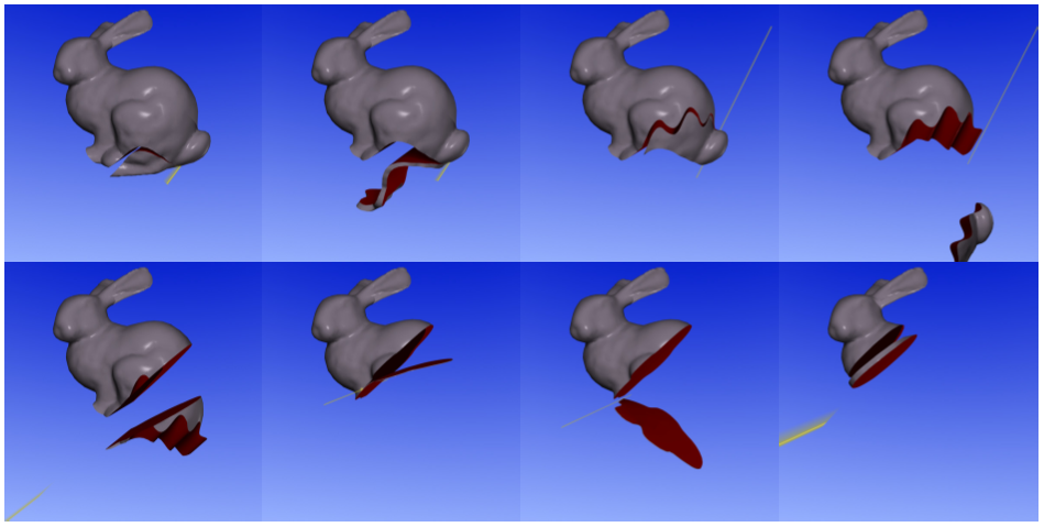
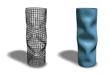
We also presented a method for simulating detailed cutting and fracturing of thin shells using low-resolution simulation meshes (Kaufmann et al., 2009). Instead of refining or remeshing the underlying simulation domain to resolve complex cut paths, we adapted the extended finite element method (XFEM) and enrich the set of shape functions by custom-designed basis functions that are discontinuous at the cut location. These enrichment functions are stored in enrichment textures, which allows for fracture and cutting discontinuities at a resolution much finer than the underlying mesh (Figure 6). In order to simulate shells with simple C0-continuous shape functions, which then can easily be enriched by XFEM, we employed Discontinuous Galerkin Kirchhoff-Love shells (Kaufmann et al., 2009).
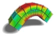
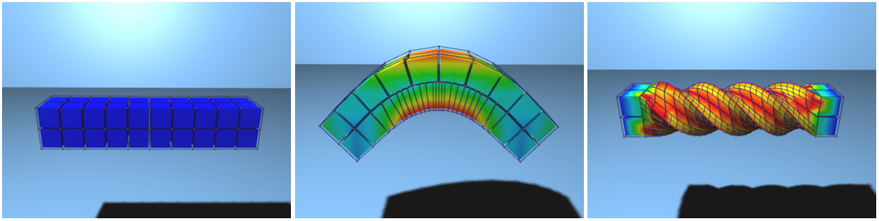
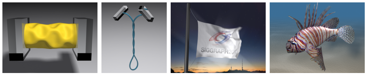
Elastic bodies take many forms, from long and slender rods, to flat and wide shells, to thick and bulky solids. In (Martin et al., 2010) we developed an accurate, unified treatment of these different types of elastic models. Following the method of resultant-based formulation to its logical extreme, we derived a higher-order integration point, the elaston, that measures stretching, shearing, bending, and twisting along any axis. An assembly of elastons accurately captures the behavior of elastic materials of any dimension. The theory and accompanying implementation do not distinguish between forms of different dimension (solids, shells, rods), nor between manifold regions and non-manifold junctions. Consequently, a single code accurately models a diverse range of elastoplastic behaviors, including buckling, writhing, cutting and merging (Figures 7,8).
Related Publications
- Unified Simulation of Elastic Rods, Shells, and SolidsACM Transaction on Graphics 29(4), (Proc. SIGGRAPH), 2010